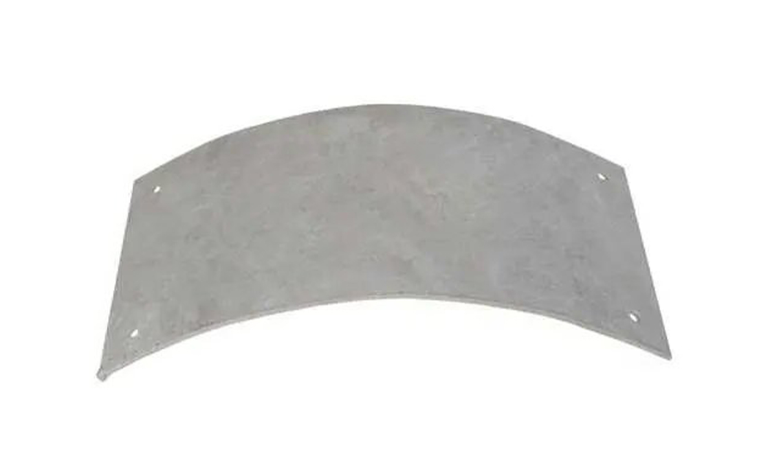
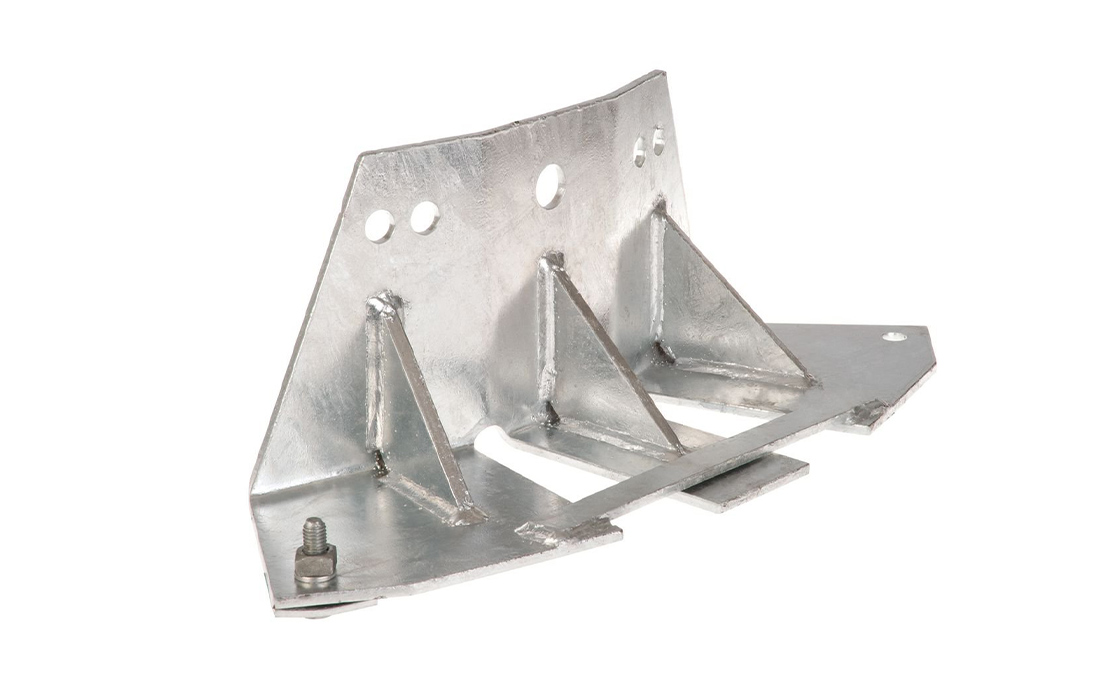
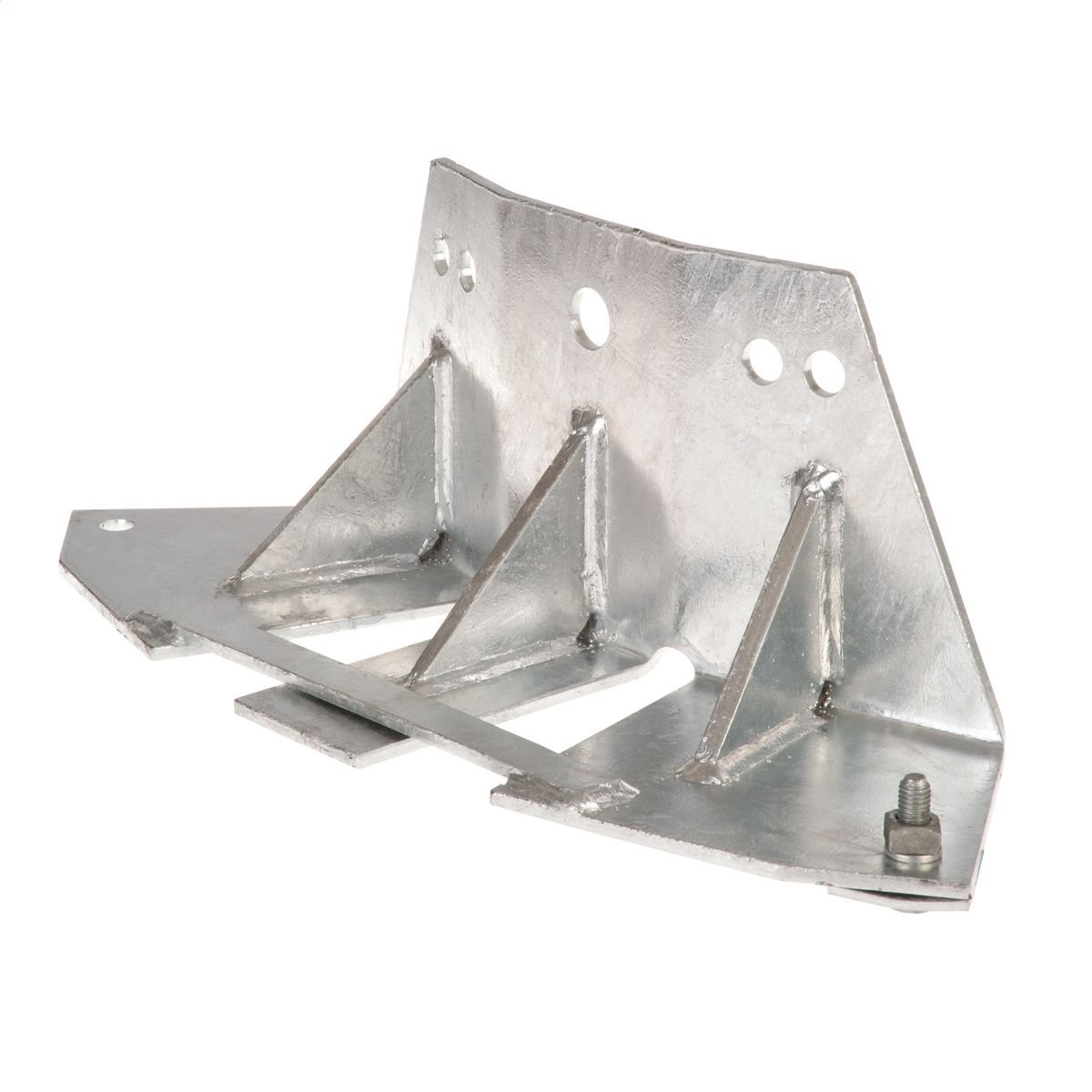
Pole Bearing Plate
- Curved galvanized steel plate buried at the base of a wood / concrete pole to prevent sinking in soft / wet soil
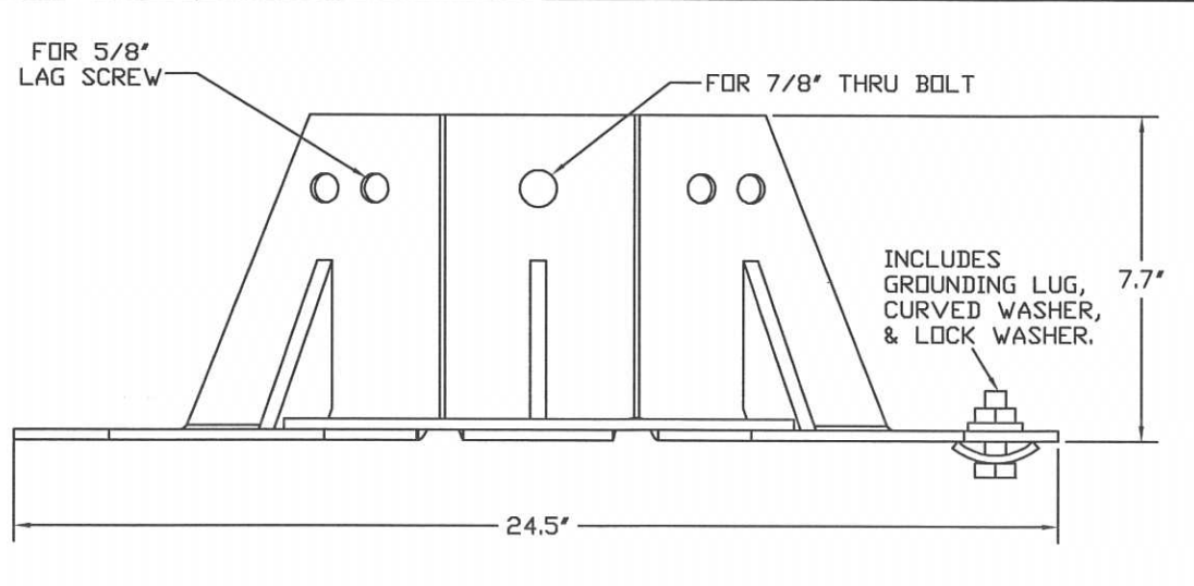
- 6 types: single-plate or 2-plate H-frame configurations with 16″ / 24″ / 28″ / 30″ thru-bolt options
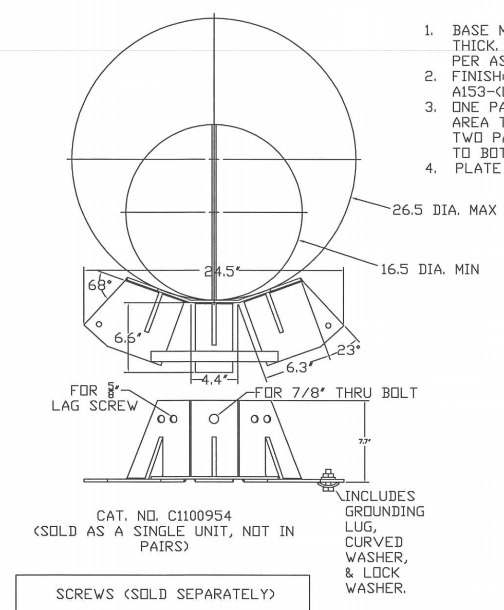
- 122 sq in bearing area per plate, fits poles 16.5–26.5″ butt diameter (Hubbell C1100954 eq.)
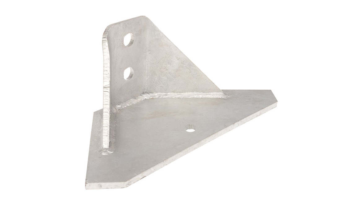
- Hot-dip galvanized per ASTM A153 Class B; includes grounding lug + curved washer + lock washer on bolted variants
Technical Specifications
| Catalog | Plate Count | Plate Geometry | Thru-Bolt | Lag Screws | Hubbell Eq. | Ship Weight (kg) |
|---|---|---|---|---|---|---|
| RAX-PBP-1 | 1 plate | 24.5″ W × 7.7″ H, 122 sq in bearing | Not included | Not included | C1100954 | 9.5 |
| RAX-PBP-2 | 2 plates | 24.5″ W × 7.7″ H each | Not included | Not included | C11009542 | 19.0 |
| RAX-PBP-2-16 | 2 plates | 24.5″ W × 7.7″ H each | 16″ (406 mm) HDG, 7/8″ thru | Not included | C1100954216 | 22.0 |
| RAX-PBP-2-24 | 2 plates | 24.5″ W × 7.7″ H each | 24″ (610 mm) HDG, 7/8″ thru | Not included | C1100954224 | 24.0 |
| RAX-PBP-2-28H | 2 plates | 24.5″ W × 7.7″ H each | 28″ (711 mm) HDG, 7/8″ thru | Included (4 × 5/8″ lag, HDG) | C1100954228H | 27.0 |
| RAX-PBP-2-30 | 2 plates | 24.5″ W × 7.7″ H each | 30″ (762 mm) HDG, 7/8″ thru | Not included | C1100954230 | 28.0 |
Application & Installation

Where it is used
- Direct-buried wood / concrete distribution and transmission poles in soft, saturated, or organic soils (clay loam, peat, marsh, lacustrine deposits) where bearing failure causes pole sinking
- H-frame transmission structures (115–345 kV) where two pole legs land in separate holes — 2-plate types tie the two legs through the thru-bolt for synchronized settlement resistance
- Permafrost / frost-heave zones (Alaska, northern Canada, Scandinavia) where seasonal freeze cycles "jack" unbraced poles upward 25–50 mm per year — the plate's lateral surface area resists upward movement
- River-crossing and shoreline structures where pole foundations sit in alluvial / hydraulically deposited soils with low bearing capacity
- Retrofit on settled existing poles (extract, inspect, install plate, re-set) to extend service life by 15–25 years vs replacement
Installation sequence (single pole, soft soil)
- Excavate the pole hole to design depth (typically 10% of pole length + 2 ft per NESC Rule 261) plus an additional 4″ for the plate thickness.
- Place the bearing plate flat at the bottom of the hole with the curved side up; the curve matches the pole's butt circumference.
- Lower the pole onto the plate using a derrick or backhoe; align the pole's lag-screw pattern with the plate's 4 × 5/8″ holes.
- Install 5/8″ × 8″ lag screws through the plate into the pole butt (4 screws minimum, torque to 80 ft·lb).
- Run the grounding conductor from the welded lug down to the buried ground rod or up the pole to the grounding bus; bond per NESC Rule 215.
- Backfill with the excavated soil in 6-inch lifts, hand-tamping each lift to 95% Proctor density — native soil over crushed stone if the original was contaminated or organic.
Buyer’s Guide: Pole Bearing Plate
1. What a Pole Bearing Plate Actually Does — Soil Bearing Math
A Pole Bearing Plate is a curved galvanized steel platform buried at the base of a utility pole that spreads the pole's vertical load over a larger soil contact area. Without it, all of the pole's downward force (own weight + line tension vertical components + ice load + accumulated water in the pole's hollow tip for steel poles) bears on the small circular pole-butt footprint — typically only 1.5–3.5 sq ft for a Class 4–1 wood pole. In soft / saturated / organic soils where the allowable bearing pressure is 1,500–3,000 psf, that small footprint exceeds soil capacity within months and the pole sinks. The bearing plate adds 122 sq in (0.85 sq ft) of additional rigid bearing area below the pole butt, increasing total contact by 25–50% and dropping the soil pressure below the allowable. This is a geotechnical fix to a soil-mechanics problem — not a hardware nicety.
2. When You Need a Plate — Soil Classification Triggers
The decision to spec a bearing plate is driven by soil class, not by routine. Per IEEE Std 691 (transmission foundation design): no plate needed for SP / GW (well-graded sand or gravel, dense, high bearing) or stiff clay (CL, CH); plate required for soft clay (CL with N<4 SPT blow count), organic clay (OL / OH), peat (PT), or any soil with seasonally high groundwater table where effective bearing capacity drops by 30–50% in saturated condition. Geotech reports from your project will specify the soil class and bearing capacity at the proposed pole depth — if the bearing pressure under the pole butt exceeds the allowable, you need a plate. For routine distribution rebuild work without site-specific geotech, the rule of thumb is: spec the plate if the soil is visibly wet, swampy, marsh-like, or contains visible organic matter (root mats, peat).
3. Single-Plate vs 2-Plate H-Frame Configurations
The single-plate type (RAX-PBP-1) is for individual pole installations — one pole, one hole, one plate. The plate sits at the bottom of the hole and the pole bears on it. 2-plate types (RAX-PBP-2 family) are for H-frame transmission structures: a horizontally-braced two-pole assembly used at 115 kV and above where one pole couldn't safely carry the conductor weight at long spans. H-frame legs land in two separate holes — one plate per leg, with a long thru-bolt connecting the two plates underground. The thru-bolt forces synchronized settlement: if one leg starts to sink faster (uneven soil), the bolt pulls the other leg down too, keeping the H-frame level. Without the bolt, differential settlement skews the frame and progressively destroys the connection joinery at the top.
4. Bolt Length Selection — The H-Frame Spacing Math
For 2-plate types, the thru-bolt length must match your H-frame leg spacing. Standard H-frame designs use 12″ / 18″ / 24″ / 30″ center-to-center pole spacing depending on conductor configuration and voltage class. Bolt length = pole spacing + 4″ (allows 2″ of bolt + nut on each plate after the plates are countersunk). Mapping: 12″ spacing → 16″ bolt (RAX-PBP-2-16); 20″ spacing → 24″ bolt (RAX-PBP-2-24); 24″ spacing → 28″ bolt with lag screws (RAX-PBP-2-28H); 26″ spacing → 30″ bolt (RAX-PBP-2-30). For non-standard spacing (40″+, used on 345 kV+ structures), order custom bolt length with the longer-bolt option — 10-day add to lead time.
5. The Grounding Lug — Why It's Welded, Not Bolted
Every Raxsteel bearing plate ships with a welded (not bolted) grounding lug on one side of the plate. Welded is the right answer here for two reasons. First, the plate is buried below the water table or in saturated soil for its entire service life — any bolted electrical connection corrodes through within 5 years, breaking ground continuity exactly when you can't access it to fix. Second, the buried plate is a ground electrode in its own right (per NEC 250.52(A)(5)) with ~80 sq in of submerged metal contact — the welded lug ties the pole's ground wire to that electrode without dependence on bolt tightness. Standard lug accepts 2 AWG to 4/0 AWG copper via a 1/2″ clamp bolt; specify 250 kcmil compatibility (option suffix -BIG) for high-current substation feeds.
6. Galvanizing for Buried Service — Why ASTM A153 Isn't Enough
ASTM A153 Class B (the standard HDG spec for pole-line hardware) calls for 86 μm minimum zinc coating — sufficient for above-ground service where the zinc passivates and protects itself for 30+ years. For permanently buried hardware in soil with chloride content (road salt zones, coastal areas) or low pH (peat, organic soils), 86 μm delivers only 8–15 years before zinc consumption exposes bare steel. Raxsteel bearing plates ship at 110 μm typical (Class B+) as the default, and for projects in known-aggressive soils we recommend the duplex coating upgrade: HDG + 4 mil coal-tar epoxy on both sides, applied at the factory after cooling. Duplex extends buried service to 50+ years and is the standard for transmission-grade specs on critical structures.