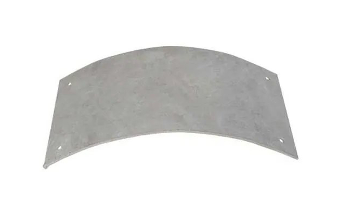
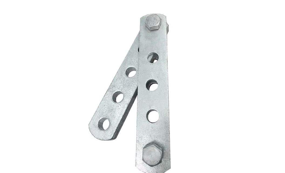
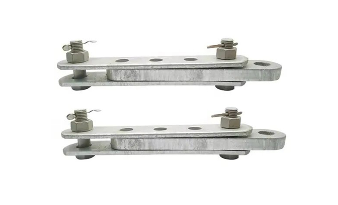
PT Type Adjusting Plate
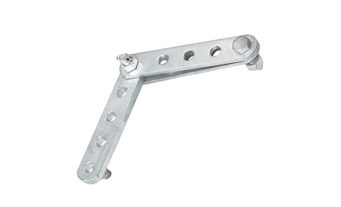
- Articulated 2-arm yoke plate (hinged at one end) for attaching insulator strings at adjustable angles in dead-end / angle structures
- 6 types covering 3-hole through 6-hole arm lengths, 70 kN through 210 kN ultimate breaking load
- Multi-hole pattern (1-1/8″ pitch) lets installer choose attachment angle from ~15° to 90° without modifying the plate
- Hot-dip galvanized forged steel arms + HDG carriage bolt hinge with cotter pin retention (GB/T 2317 / IEC 61284 eq.)
Technical Specifications
| Catalog | Holes / Arm | Arm Length | Hole Diameter | UTS Rating | Application Class | Wt (kg) |
|---|---|---|---|---|---|---|
| RAX-PT-70 | 3 | 120 mm (4.7″) | 12 mm (0.47″) | 70 kN | Distribution 11–33 kV | 0.85 |
| RAX-PT-100 | 4 | 150 mm (5.9″) | 16 mm (0.63″) | 100 kN | Sub-transmission 66 kV | 1.40 |
| RAX-PT-120 | 4 | 180 mm (7.1″) | 16 mm (0.63″) | 120 kN | Sub-transmission 110 kV | 1.85 |
| RAX-PT-160 | 5 | 220 mm (8.7″) | 20 mm (0.79″) | 160 kN | Transmission 132 kV | 2.65 |
| RAX-PT-180 | 5 | 240 mm (9.4″) | 20 mm (0.79″) | 180 kN | Transmission 220 kV | 3.10 |
| RAX-PT-210 | 6 | 280 mm (11.0″) | 20 mm (0.79″) | 210 kN | Transmission 220 kV heavy | 3.85 |
Application & Installation

Where it is used
- Angle structures (10°–60° line direction changes) where the conductor pull angle and insulator string angle don't match cleanly
- Double dead-end structures (transposition poles, substation entry / exit) where two insulator strings converge at angles other than 90°
- Tap-off structures where a feeder branches at an angle and the tap conductor needs a separately-angled insulator string
- River-crossing / long-span structures with steep upward conductor angles where standard 90° yoke plates would mis-load the insulator caps
- Retrofit applications where line reconductoring changed the conductor weight / angle and the original fixed yoke plates over-load the insulators
Installation sequence (RAX-PT-100, 66 kV angle dead-end)
- De-energize the line and rig the conductor to the dead-end's temporary support (preformed dead-end grip + tackle to the structure).
- Position the adjusting plate at the structure's yoke point; the hinge end attaches to the structure's arm via a 16 mm clevis bolt + cotter pin.
- Identify the design insulator string angle from the line geometry drawing — typically 15° / 30° / 45° off vertical for the chord side of an angle structure.
- Open the adjusting plate to that angle by swinging the lower arm; insert the 16 mm clevis bolt through the matching hole pair (use the hole at the design angle).
- Mount the insulator string's top clevis tongue on the lower arm using the clevis bolt; verify the string hangs cleanly at the design angle without binding.
- Re-tension the conductor to design sag; the plate's angle is now locked by the conductor tension acting through the insulator string.
Buyer’s Guide: PT Type Adjusting Plate
1. What an Adjusting Plate Solves — The Angle Mismatch Problem
Most transmission and distribution line geometry is straight: conductors run perpendicular to the crossarm, insulator strings hang vertically from the yoke, no special hardware needed. The complication shows up at angle structures (where the line changes direction by 10° or more) and dead-end structures (where two line sections converge or one terminates). At these structures, the conductor's pull angle doesn't match the insulator string's natural hanging angle — if you bolt the insulator directly to a fixed yoke plate, the string is loaded eccentrically, the porcelain caps fracture within months, and the dead-end fails. The PT Type Adjusting Plate solves this with a hinge: two arms swing relative to each other to whatever angle the line geometry demands, the insulator string hangs straight down from the hinge axis regardless. The plate is the geometric adapter that lets standard insulator strings work at any line angle.
2. Selecting by UTS Rating — Conductor Tension Math
The plate's UTS (Ultimate Tensile Strength) rating must exceed the design conductor tension by a safety factor of 2.5× (per IEEE 691 / GB 50545). Typical conductor tensions: ACSR Penguin (4/0) at 30% NESC Heavy load: ~14 kN per phase → needs minimum 35 kN UTS plate → RAX-PT-70 (70 kN UTS, 5× safety factor). ACSR Drake (795 kcmil) at 30% NESC Heavy: ~40 kN per phase → needs minimum 100 kN UTS → RAX-PT-100. Bundled ACSR Cardinal (954) 2-conductor at 30%: ~95 kN per bundle → needs minimum 240 kN UTS → use 2 × RAX-PT-180 in parallel or step up to custom 280 kN. Over-spec by one class for cold-climate ice-load zones; under-spec causes catastrophic dead-end failures.
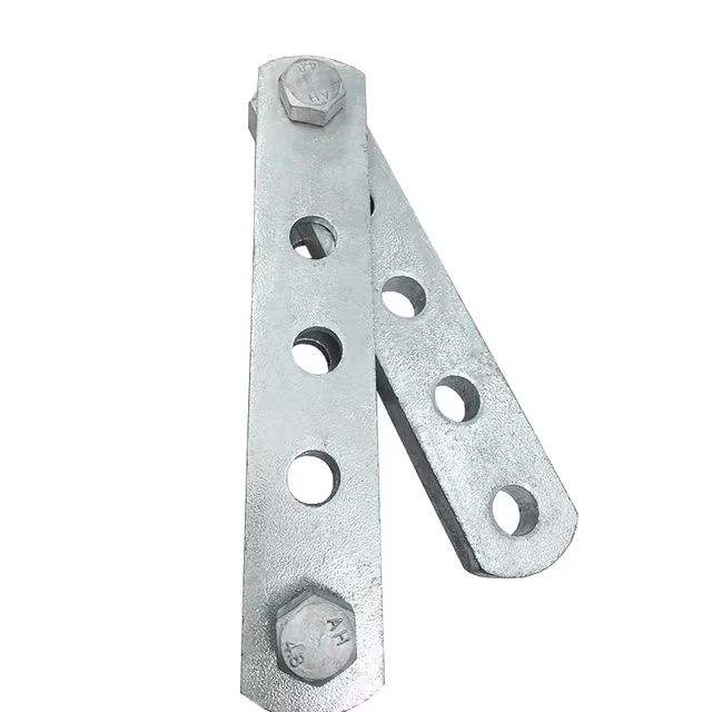
3. Hole Pattern & Angle Adjustment Range
The arm's hole pattern (1-1/8″ / 30 mm pitch) maps directly to discrete angle adjustments. 3-hole arm (RAX-PT-70): 3 angle positions (0° / 30° / 60° from arm axis) — enough for typical distribution dead-ends. 4-hole (RAX-PT-100, -120): 4 positions, finer adjustment for sub-transmission. 5-hole (RAX-PT-160, -180): 5 positions covering the 15°–75° range typical of transmission angle structures. 6-hole (RAX-PT-210): 6 positions for 220 kV+ structures with unusual geometry. Match arm length to your angle range: longer arms = more adjustment positions but more wind drag and more steel cost.
4. Forged Steel vs Stamped — Why Forged Wins for High Loads
Cheaper imported adjusting plates are stamped from flat sheet steel with the hinge formed by bending tabs. They're ~40% cheaper but have two failure modes utility specs flag: the bent hinge tab fatigues at the bend radius under cyclic conductor swing, and the stamped arms lose strength at the hole edges where the punch fractured the steel grain. Raxsteel adjusting plates use drop-forged steel arms (BS EN 10025-2 S355JR, hot-die forged at 1100°C then normalized) with the holes drilled and reamed after forging. The arms are grain-aligned along the load axis, holes have no fracture surface, and the UTS ratings are guaranteed minimums after destructive testing on 1 of every 50 production units. Cost premium over stamped: ~$3 per plate — trivial relative to the catastrophic-failure cost of a stamped plate fracturing in service.
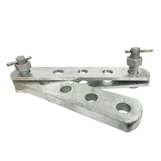
5. Hinge Bolt & Cotter Pin — The Maintenance Window
The hinge bolt is not a load-bearing element in normal service — it's a pivot pin. Load is carried through the connecting clevis bolts at whichever hole pair the installer chose; the hinge just keeps the two arms from separating during install / re-tension operations. Because of this, the hinge bolt can be removed for service inspection without de-energizing the line, IF the connecting clevis bolts are in place and tightened. Inspection schedule: visually check the hinge bolt and cotter pin every 5 years; if the cotter pin shows red rust or the hinge bolt rotates freely (vs the design slight friction), replace both. Replacement is hot-stick possible: a 16 mm cotter pin extractor + new bolt + new pin, ~10 minutes per plate.
6. Insulator Clevis Compatibility — ANSI vs IEC vs Hubbell Y-Plate Pins
The plate's arm holes are sized for standard insulator clevis tongue bolts: 12 mm for distribution-class insulators (66–132 kN MFL), 16 mm for sub-transmission, 20 mm for transmission-class (300+ kN MFL). These match ANSI C29.2 clevis dimensions for North American insulators and IEC 61466 clevis tongue specs for European / international insulators. For Hubbell Y-plate compatible installations, the 20 mm hole accepts Hubbell's standard yoke pin (7/8″ nominal). For unusual insulator clevises (some older porcelain disc strings, transmission-class composite insulators with proprietary clevis pins), specify the bolt diameter at PO and we'll drill/ream the holes to match before galvanizing.