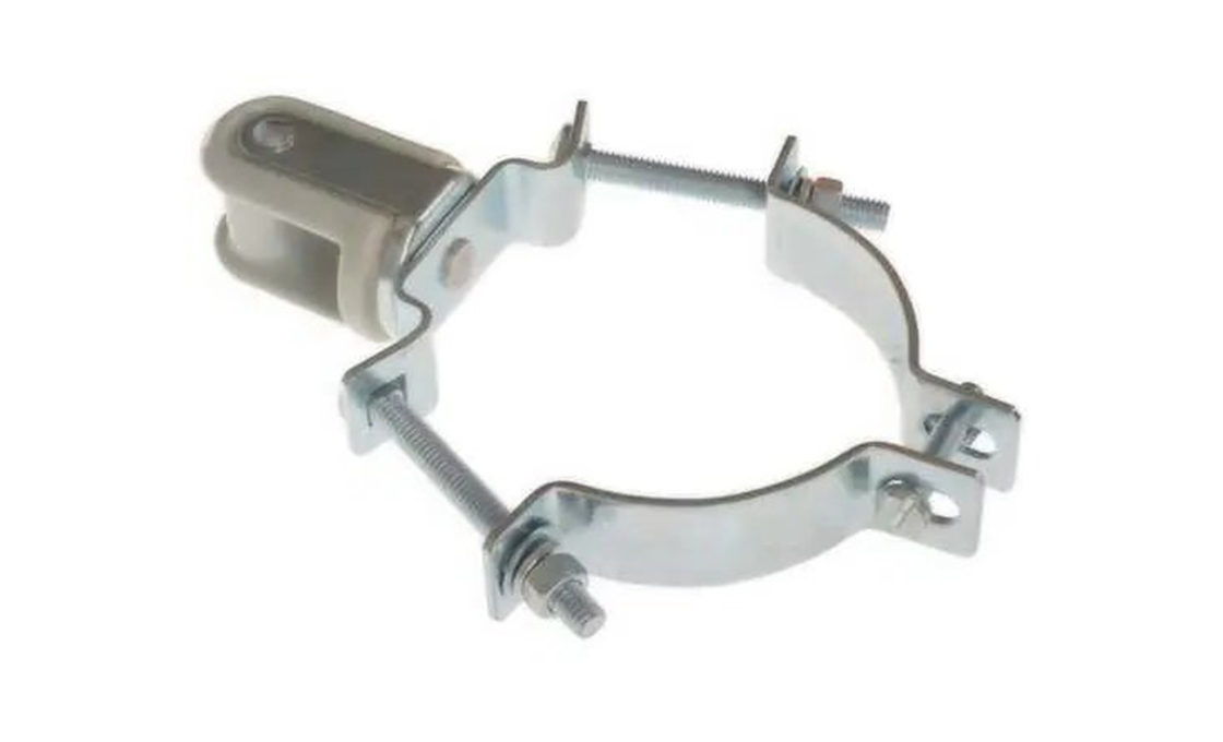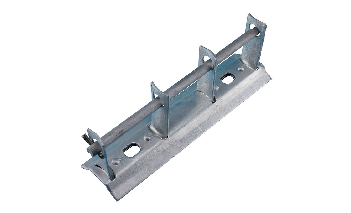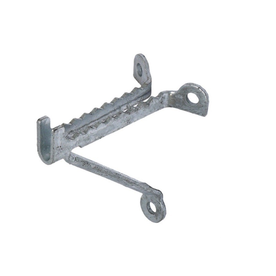
Screw Type Wireholder
- Compact galvanized cast bracket with toothed saddle — lag-bolts directly to a wood building wall or pole to hold the service drop conductor
- 5 types covering 2″ to 4″ saddle widths for AWG 8 through 4/0 service drop sizes
- The simplest, lowest-cost service drop attachment — no mast required, no separate insulator (toothed saddle bites into conductor)
- Hot-dip galvanized cast iron per ASTM A153; ships with 2 × 3/8″ HDG lag screws (5/8″ pilot hole)
Technical Specifications
| Catalog | Saddle Width | Saddle Depth | Max Conductor | Lag Screw Holes | Hubbell / Allied Eq. | Wt (kg) |
|---|---|---|---|---|---|---|
| RAX-SWH-2 | 2″ (51 mm) | 0.6″ (15 mm) | AWG 8 triplex (0.45″ OD) | 2 × 3/8″ | Hubbell EWH-2 / Allied 5410 | 0.20 |
| RAX-SWH-25 | 2-1/2″ (64 mm) | 0.7″ (18 mm) | AWG 6 triplex (0.55″ OD) | 2 × 3/8″ | Hubbell EWH-3 | 0.25 |
| RAX-SWH-3 | 3″ (76 mm) | 0.8″ (20 mm) | AWG 1/0 triplex (0.65″ OD) | 2 × 3/8″ | Hubbell EWH-4 eq. | 0.32 |
| RAX-SWH-35 | 3-1/2″ (89 mm) | 0.9″ (23 mm) | AWG 2/0 quadruplex (0.75″ OD) | 2 × 3/8″ | Hubbell EWH-5 | 0.40 |
| RAX-SWH-4 | 4″ (102 mm) | 1.0″ (25 mm) | AWG 4/0 quadruplex (0.85″ OD) | 2 × 3/8″ | Hubbell EWH-6 | 0.55 |
Application & Installation

Where it is used
- Residential overhead service entrances where the customer side terminates on a wood building wall (no mast required)
- Small commercial buildings (single-story retail, garages, workshops) with overhead service from a roadside utility pole
- Outbuildings (detached garages, barns, sheds) receiving a secondary feed from the main building
- Pole-to-pole secondary distribution where the conductor needs intermediate support along its route (mid-span saddles)
- Retrofit replacement of failed insulator-style wireholders where the building owner prefers the cheaper, simpler screw-type rebuild
Installation sequence (RAX-SWH-3 on wood building wall)
- Confirm the service drop attachment height meets NEC 230.24: minimum 10 ft above grade, 12 ft over driveways, 15-1/2 ft over public streets.
- Mark the 2 lag screw positions on the wood wall (vertical alignment, 4″ on-center spacing); pilot-drill 5/8″ diameter holes, 3-1/2″ deep.
- Position the wireholder against the wall with the toothed saddle facing the utility pole; insert the 2 × 3/8″ lag screws + flat washers through the holder's mounting holes into the pilot holes.
- Tighten the lag screws alternately (top, bottom, top, bottom) to 60 ft·lb torque — the holder should sit flush against the wood with no gap.
- Lay the service drop conductor across the toothed saddle from the outboard side; gently work the conductor down into the saddle teeth using gloved hands (the teeth will bite the conductor jacket as it seats).
- For drops over 100 A or in high-wind zones, add a preformed dead-end grip to the conductor 6″ above the saddle as a secondary anchor — ties the conductor back to the holder's upper mounting hole.
Buyer’s Guide: Screw Type Wireholder
1. What the Screw-Type Wireholder Actually Does — The No-Mast Approach
The Screw-Type Wireholder is the simplest possible service-drop attachment for residential overhead service. Where the Porcelain Mast Mounted Wireholder requires a rigid service mast (RMC pipe) and a separate insulator + dead-end grip, the screw-type does everything in one cast piece: the toothed saddle grips the conductor (no separate insulator), and two lag screws fix it to the wood building wall (no mast required). Cost is ~1/3 of the mast-mounted approach, install time is ~5 minutes. The tradeoff: no electrical isolation (the cast iron holder IS bonded to the conductor it grips), so the screw-type is only used where the conductor jacket itself provides the insulation — standard for triplex / quadruplex secondary service drops with thermoplastic insulation, but NOT for bare-conductor primary or any medium-voltage application.
2. Saddle Width Selection — Match Conductor OD
The saddle's inside width must match the conductor's outside diameter within +/-0.05″ tolerance. Too narrow: the conductor sits on the saddle rim, not in the teeth — slips out under tension. Too wide: the saddle teeth don't engage the conductor jacket — same slip-out failure mode. The mapping in the type table is the manufacturer's spec: RAX-SWH-2 for AWG 8 triplex (the smallest standard residential drop, ~30 A), RAX-SWH-3 for 1/0 triplex (100 A residential, the dominant size in US distribution), RAX-SWH-4 for 4/0 quadruplex (200 A 3-phase commercial). When in doubt about the conductor OD, measure with calipers across the triplex bundle's widest dimension and add 5%.
3. Wood Pole / Wall Compatibility — Lag Screw Embedment
The 3/8″ lag screws need solid wood depth of at least 3 inches for full holding power. Typical 2″×6″ or 2″×4″ framing behind 7/8″ wood siding gives the required 3″ of solid wood — works for the vast majority of residential installations. Stucco or aluminum siding over a wood-frame wall works the same way (the siding doesn't provide hold, the underlying wood does). Brick / masonry / concrete walls need the masonry kit version (suffix -MK) with 3/8″ expansion anchors instead of lag screws. Vinyl siding over thin wood (1/4″) does NOT have adequate hold — install a 5/8″ backing block first, then mount the wireholder to the backing.
4. Cast Iron Saddle Teeth — Why They Bite, Why They Don't Damage
The saddle teeth look aggressive (they ARE; that's the point), but they're engineered to grip the conductor's jacket without penetrating to the metal beneath. The teeth are cast at ~30° rake angle with rounded peaks (the casting tool radius is 0.015″ minimum); under static service-drop tension (typically 80–200 lb), the teeth deform the jacket by ~0.020″ depth, which is well within the jacket's standard thickness (0.060″ for typical triplex). The deformation is permanent but not damaging — the conductor metal is never exposed, no moisture entry path is created, and the indentation gives the holder its grip. Conductor jacket NEC compliance (UL 854 service-drop cable spec) explicitly anticipates this contact pattern.
5. When NOT to Use Screw-Type — The Mast-Required Cases
Two scenarios force the more expensive mast-mounted approach. First: the customer's service entrance is on the upper floor of a multi-story building, requiring the service drop to enter at 25+ ft above grade; a service mast extends upward from the meter base to the required height, and the screw-type doesn't apply because there's no wood wall at the right elevation. Second: the building is brick or block construction with NO wood framing; the masonry kit (-MK suffix) works on brick but doesn't address the lack of insulation between the energized conductor and the grounded steel inside the wall — for those, mast-mount with a separate insulator is code-required. Otherwise, screw-type is the default, cheaper, faster choice.
6. Galvanizing & the Cast Iron Corrosion Cycle
Standard screw-type wireholders are hot-dip galvanized cast iron (specifically malleable iron per ASTM A47) at ~86 μm zinc coating. In residential / coastal-inland service, expect 25–35 year service life before the zinc depletes and red rust appears on the casting surface. Once red rust shows, the holder still works mechanically for another 5–10 years — rust doesn't reduce the saddle's grip on the conductor — but utilities typically replace on inspection schedule rather than wait for actual failure. For aggressive coastal environments (within 1 mile of saltwater) or industrial sites, specify duplex coating (HDG + epoxy paint, +$1.50/holder) to extend service to 50+ years; the epoxy chips reveal the still-protective zinc beneath, so a chipped duplex holder still outlasts a brand-new standard HDG holder in those environments.